STATUS OF A WORKING RPLG BOX FOR PNP
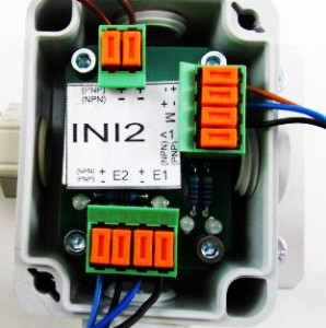
 This photo shows a completely wired RPLG 2 for PNP sensors. The LEDs above the lower terminal are illuminated, indicating that each input receives a signal from a sensors of a GRZ gripper. The illuminated LED next to the lower terminal indicates that the RPLGs output is HIGH. The dark LED next to it illuminates when non of the RPLG inputs are HIGH.
How to wire a RPLG for PNP Sensors
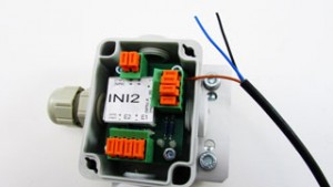
 Every RPLG features blade style terminals. Do not strip the isolation, just lift up the orange terminals, using a small screw driver and insert the wire. Then press hard on the orange terminal, you will feel how the knife cuts into the isolation of the wire. TIP: Remove the board from the box, strip the wires 3 inches (75mm) and then insert them into the box. All wires will rest underneath the board.
Commonly used Color Code:
+24 V = Brown
(-) = Blue
Signal = Black
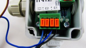
 The terminals on the bottom connect from right to left: E1 = Input 1 black (signal) wire from sensor1, (-) blue wire from Sensor 1 , E2= Input 2 black (signal) wire from sensor 2, (-) blue wire from sensor 2
The terminal on the top, connects the +24V brown wires from the sensors.
The terminal on the right connects the RPLG to the robot or PLC controller. From top to bottom: (+) brown wire is the positive feed for the RPLG box. (-) the blue wire is the negative or common from the robot or PLC. (M) the black wire is the RPLG output (all sensors are ON) Terminal (<1) is not being used but this terminal is HIGH when ALL sensors (inputs) are low.
Remarks:
Unused inputs need to be jumped in order to make the RPLG functional. Connect the free (+) terminal at the top with the free (E) terminal
You can run several RPLGs in series. Use the output (M) from one box and connect it with any Input (E) of the next RPLG
